Autorotation
The most common reason to perform an
autorotation is engine failure. But autorotation is also performed during
complete tail rotor failure as it produces virtually no torque, and a safe
landing is possible.
At the instant of engine failure or tail
rotor failure, the main rotor blades are producing lift and thrust from their
AOA and velocity. By immediately lowering the collective pitch, the lift and drag
of the helicopter are lowered and the helicopter begins to descend producing an upward
flow of air through the rotor system immediately. This upward flow provides sufficient thrust
to maintain rotor rpm throughout the descent.
Airspeed and rotor rpm are the primary
ways to control the rate of descent in autorotation. Higher or lower airspeed is
obtained with the cyclic pitch control just as in normal powered flight. The rate of descent is high at zero airspeeds
and decreases to a minimum at approximately 50–60 knots (depending upon the particular
helicopter), beyond which the rate of descent starts to increase again.
When landing from an autorotation, the
only energy available to arrest the descent rate and ensure a soft landing is the kinetic energy obtained from the descent. Since the tail rotor is driven
by the main rotor transmission during autorotation, the heading is maintained with
the tail rotor as in normal flight.
In normal powered helicopter flight, the air is drawn into the main rotor system from above and exhausted downward. But during autorotation, air moves up into the rotor system from below as the aircraft descends
If the engine fails during a hover in
still air and the collective pitch is reduced, the helicopter will accelerate
downwards until such time as the angle of attack is producing a total reaction
to give an autorotative force to maintain the required rotor rpm and a rotor
thrust equal to the weight.
The pilot should use collective pitch control to manage rotor rpm. If
rotor rpm builds too high during an autorotation, pilot should raise the
collective sufficiently to decrease rpm back to the normal operating range,
then reduce the collective to maintain proper rotor rpm. If the collective increase is held too long, the rotor rpm may decrease rapidly.
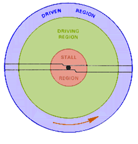
During Vertical autorotation, the rotor disk is divided into three regions are the driven region, the driving region, and the stall region.
The rate of descent is the same for all sections. Rotational velocity will decrease from the tip towards the root. Comparing these sections, the inflow angle must therefore be progressively increasing
The following project link will redirect to the project page which can also be viewed on mobile. It explains the phenomenon of Autorotation step by step. The steps can be repeatedly viewed back and forth as per the will of the user.
 |
| Autorotation on Scratch |
Click the Next Button to see and understand the different conditions that are going through the phases of autorotation.
The rotor blade is divided basically into 3 sections.
The Phases of Autorotation can be easily visualized using the next or previous buttons.


Comments
Post a Comment